
If you’re a hardware hobbyist looking to explore custom electronics projects, building your own cables can be a rewarding experience. One project that has intrigued many enthusiasts is creating a Dell CT109 Serial to PS2 cable. This custom cable can bridge the gap between older and newer tech, breathing new life into legacy devices.
This guide takes you step-by-step through the process of making a Dell CT109 Serial to PS2 cable, from understanding pinouts to ensuring safety during assembly. By the end, you’ll have the skills and knowledge to successfully complete this project while expanding your expertise in hardware tinkering.
Understanding the Dell CT109 Serial to PS2 Cable
Before we begin, it’s important to understand what this cable does. The Dell CT109 Serial to PS2 cable essentially converts data signals from a serial port into the format compatible with PS2 devices. This has been particularly useful for connecting legacy hardware, such as serial-based systems, to PS2 peripherals like keyboards or mice.
Creating this cable involves understanding the pin configurations of both connectors and ensuring proper signal matching. Let’s break this down further.
Understanding the Pinouts
Dell CT109 Serial Pinout
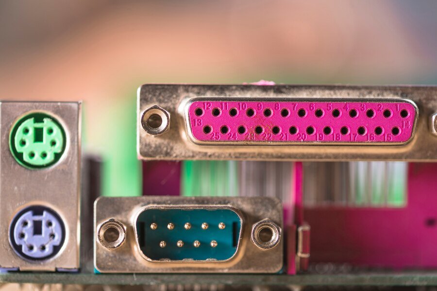
The Dell CT109 serial connector typically has a 9-pin (DB9) configuration. Here are the common pin assignments you’ll need to work with:
- Pin 2 – Receive Data (RX)
- Pin 3 – Transmit Data (TX)
- Pin 5 – Ground (GND)
Other pins may serve additional functions depending on the device, but these three are essential for most cases.
PS2 Connector Pinout
The PS2 connector, a 6-pin mini-DIN, has the following key pin assignments:
- Pin 1 – Data
- Pin 3 – Ground (GND)
- Pin 4 – Voltage (VCC, +5V)
- Pin 5 – Clock
Matching these pins between the serial and PS2 interfaces is crucial for the cable to work. Be sure to reference a reliable pinout diagram for both connectors during the process.
Hardware and Tools Required
For a smooth assembly process, gather the following tools and hardware before you begin:
Hardware
- Dell CT109 Serial Connector (DB9 plug)
- PS2 Connector (6-pin mini-DIN plug)
- Insulated wires (preferably 22-24 AWG)
- Heat shrink tubing or electrical tape
Tools
- Soldering iron and solder
- Wire strippers
- Multimeter
- Small clamps or a helping hand tool
- Heat gun (if using heat shrink tubing)
Having these tools on hand not only makes the process easier but also ensures a clean and professional-looking build.
Step-by-Step Guide to Making the Cable
Step 1: Prepare Your Workspace
Set up a clean, well-lit workspace. Make sure you have adequate ventilation if using a soldering iron. Organize your tools so everything is easy to reach.
Step 2: Strip and Prepare the Wires
- Cut your wires to the desired length for your cable (around 6–8 inches should work for most setups).
- Use wire strippers to expose about 1–1.5 cm of copper on each end of the wires.
Step 3: Solder the Wires to the Serial Connector
- Identify the corresponding pins on the DB9 (serial) connector.
- Solder the wires to the appropriate pins based on the pinout:
- Pin 2 (RX) to corresponding PS2 pin
- Pin 3 (TX) to corresponding PS2 pin
- Pin 5 (GND) to PS2 ground pin
Ensure strong, secure solder joints to avoid loose connections.
Step 4: Solder the Wires to the PS2 Connector
- Locate the pins on the PS2 connector.
- Solder the wires to the PS2 pins, ensuring proper matches with the DB9 signals (e.g., data from RX connects to PS2 data pin).
Step 5: Insulate the Connections
- Cover the solder joints with heat shrink tubing. If not available, use electrical tape.
- Use a heat gun to shrink the tubing securely.
This will prevent short circuits and improve the cable’s durability.
Step 6: Test the Cable
- Use a multimeter to test continuity. Verify that each pin on the serial connector is properly connected to its corresponding pin on the PS2 connector.
- Double-check for crossed wires or incorrect connections.
Step 7: Enclose the Connectors
- Close the connectors (if they come with covers) to protect the pins and wiring. This step also provides a polished, professional appearance to your cable.
Troubleshooting Tips
Building a cable can sometimes involve a bit of trial and error. Here’s how to overcome common issues:
- Problem: No signal is transmitted.
Solution: Check for mismatched pin configurations. Use your multimeter to confirm correct connections.
- Problem: Signal interference or unreliable performance.
Solution: Ensure all solder joints are strong and insulated. Loose or exposed connections can cause signal issues.
- Problem: Short circuits.
Solution: Recheck insulation. Make sure none of the soldered joints are touching unnecessarily. Use fresh heat shrink tubing if needed.
Safety Precautions
Safety should always be a priority when working with electronics. Keep the following tips in mind:
- Wear safety glasses to protect your eyes while soldering.
- Work in a well-ventilated area to avoid inhaling solder fumes.
- Use caution when handling the heated soldering iron—it can cause burns.
- Double-check that no wires are connected to live power sources while working on this project.
Encourage Exploration and Future Projects
Congratulations! You’ve successfully built your very own Dell CT109 Serial to PS2 cable. Not only have you created a functional cable, but you’ve also sharpened your soldering and electronics skills, laying a foundation for more complex projects.
Next, consider experimenting with other custom cables or integrating your tech into larger DIY projects. Share your experiences with fellow hardware enthusiasts to expand the community’s knowledge—and don’t forget to keep learning and building!